Product Description
Gravity die-casting
Specification:
Gravity die casting
1. Open mould
2. Die casting
3. Casting (trim, grind, drill)
4. Surface treatment( anodize, chrome-plated)
Gravity die casting
Technological processed: Open mould— die casting —-casting (trim, grind, drill) —surface treatment
Gravity die casting detail:
1. Material: Aluminum (A380, A360, ADC12, ADC10) according to JISH5302: 2006 &ASTM
2. Process: Trim grind, drill, CNC
3. Surface treatment: Shot blashing, sandblasting or painting, anodize, electroplating, chrome-plated or all per customers’ requirement
Gravity die casting design & mold manufacture
2. Use the software: Auto CAD, RPO/Engineer, Solidwork, UG
3. Mold design
4. Trial the mold
5. Machine: EDM, CNC, Grinding Machine, Milling Machine, Tuning Machine, Wire Cutting Machine, Photo Engraving, Chemical Milling, Welder
| Item | description |
| type | Aluminum die casting Zinc die casting Magnesium die casting |
| manufature | HangZhouxinlong CZPT trade co., ltd |
| equipment | Cold chamber die casting machine |
| Machine capacity | 100T-800T |
| process | Tooling making: 20-30days tooling leadtime Casting: remove all burrs & sharp edges Machinng: CNC maching, milling, drilling, trimming, cutter, griding, wire cutter etc Surface treatment: shot blasting, sand blasting Polishing, powder coating, painting, , polishing, powder coating, chrome plating, nickel plating, passivating |
| Quality control | first checked after cast from die casting machine second checked by the warehouse people third checked after machining and surface finish. We check piece by piece each time |
| package | inner packing: PE bag or air bubble bag outer packing: double corrugated carton as per customers’ requirment |
| advantage | OEM service offered Send us you RFQ in details! We produce strictly according to customer’ s design and machining request. |
| Condition: | New |
|---|---|
| Certification: | CE, RoHS, GS, ISO9001 |
| Standard: | DIN, ASTM, GOST, GB, JIS, ANSI, BS |
| Customized: | Customized |
| Material: | Aluminum |
| Application: | Metal Recycling Machine, Metal Cutting Machine, Metal Straightening Machinery, Metal Spinning Machinery, Metal Processing Machinery Parts, Metal forging Machinery, Metal Engraving Machinery, Metal Drawing Machinery, Metal Coating Machinery, Metal Casting Machinery |
| Samples: |
US$ 1/Piece
1 Piece(Min.Order) | |
|---|
| Customization: |
Available
| Customized Request |
|---|

Can you provide examples of machinery that use worm gears?
Worm gears are utilized in various machinery and mechanical systems where precise motion control, high gear reduction ratios, and self-locking capabilities are required. Here are some examples of machinery that commonly use worm gears:
- Elevators: Worm gears are commonly employed in elevator systems to control the vertical movement of the elevator car. The high gear reduction ratio provided by worm gears allows for smooth and controlled lifting and lowering of heavy loads.
- Conveyor systems: Worm gears are used in conveyor systems to drive the movement of belts or chains. The self-locking nature of worm gears helps prevent the conveyor from back-driving when the power is turned off, ensuring that the materials or products being transported stay in place.
- Automotive applications: Worm gears can be found in automotive steering systems. They are often used in the steering gearboxes to convert the rotational motion of the steering wheel into lateral movement of the vehicle’s wheels. Worm gears provide mechanical advantage and precise control for steering operations.
- Milling machines: Worm gears are utilized in milling machines to control the movement of the worktable or the spindle. They offer high torque transmission and accurate positioning, facilitating precise cutting and shaping of materials during milling operations.
- Lifts and hoists: Worm gears are commonly employed in lifting and hoisting equipment, such as cranes and winches. Their high gear reduction ratio allows for the lifting of heavy loads with minimal effort, while the self-locking property prevents the load from descending unintentionally.
- Rotary actuators: Worm gears are used in rotary actuators to convert linear motion into rotary motion. They are employed in various applications, including valve actuators, robotic arms, and indexing mechanisms, where controlled and precise rotational movement is required.
- Packaging machinery: Worm gears find application in packaging machinery, such as filling machines and capping machines. They assist in controlling the movement of conveyor belts, rotating discs, or cam mechanisms, enabling accurate and synchronized packaging operations.
- Printing presses: Worm gears are utilized in printing presses to control the paper feed and the movement of the printing plates. They provide precise and consistent motion, ensuring accurate registration and alignment of the printed images.
These are just a few examples, and worm gears can be found in many other applications, including machine tools, textile machinery, food processing equipment, and more. The unique characteristics of worm gears make them suitable for various industries where motion control, high torque transmission, and self-locking capabilities are essential.

How do you calculate the efficiency of a worm gear?
Calculating the efficiency of a worm gear involves analyzing the power losses that occur during its operation. Here’s a detailed explanation of the process:
The efficiency of a worm gear system is defined as the ratio of output power to input power. In other words, it represents the percentage of power that is successfully transmitted from the input (worm) to the output (worm wheel) without significant losses. To calculate the efficiency, the following steps are typically followed:
- Measure input power: Measure the input power to the worm gear system. This can be done by using a power meter or by measuring the input torque and rotational speed of the worm shaft. The input power is usually denoted as Pin.
- Measure output power: Measure the output power from the worm gear system. This can be done by measuring the output torque and rotational speed of the worm wheel. The output power is usually denoted as Pout.
- Calculate power losses: Determine the power losses that occur within the worm gear system. These losses can be classified into various categories, including:
- Mechanical losses: These losses occur due to friction between the gear teeth, sliding contact, and other mechanical components. They can be estimated based on factors such as gear design, materials, lubrication, and manufacturing quality.
- Bearing losses: Worm gears typically incorporate bearings to support the shafts and reduce friction. Bearing losses can be estimated based on the bearing type, size, and operating conditions.
- Lubrication losses: Inadequate lubrication or inefficient lubricant distribution can result in additional losses. Proper lubrication selection and maintenance are essential to minimize these losses.
- Calculate efficiency: Once the power losses are determined, the efficiency can be calculated using the following formula:
Efficiency = (Pout / Pin) * 100%
The efficiency is expressed as a percentage, indicating the proportion of input power that is successfully transmitted to the output. A higher efficiency value indicates a more efficient gear system with fewer losses.
It is important to note that the efficiency of a worm gear can vary depending on factors such as gear design, materials, lubrication, operating conditions, and manufacturing quality. Additionally, the efficiency may also change at different operating speeds or torque levels. Therefore, it is advisable to consider these factors and conduct efficiency calculations based on specific gear system parameters and operating conditions.

Understanding Worm Gears and Their Operation
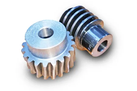
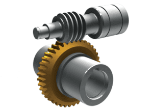
A worm gear is a type of mechanical gear that consists of a threaded screw-like component (called the worm) and a toothed wheel (called the worm gear). It is used to transmit motion between non-intersecting and perpendicular shafts. Here’s how it works:
The worm, typically in the form of a cylindrical rod with a helical thread, meshes with the teeth of the worm gear. When the worm is rotated, its threads engage with the teeth of the worm gear, causing the gear to rotate. The direction of rotation of the worm gear is perpendicular to the axis of the worm.
One significant feature of worm gears is their ability to provide high gear reduction ratios. The number of teeth on the worm gear relative to the number of threads on the worm determines the reduction ratio. This makes worm gears suitable for applications where high torque and low-speed rotation are required.
Worm gears are commonly used in various mechanical systems, such as conveyor systems, lifts, automotive steering mechanisms, and more. Their unique design also provides a self-locking feature: when the system is not actively rotating the worm, the gear cannot easily backdrive the worm due to the angle of the threads, providing mechanical advantage and preventing reverse motion.


editor by CX 2023-09-10