Product Description
Product Description
Main Materials:
1)housing:aluminium alloy ADC12(size 571-090); die cast iron HT200(size 110-150);
2)Worm:20Cr, ZI Involute profile; carbonize&quencher heat treatment make gear surface hardness up to 56-62 HRC; After precision grinding, carburization layer’s thickness between 0.3-0.5mm.
3)Worm Wheel:wearable stannum alloy CuSn10-1
Detailed Photos
Combination Options:
Input:with input shaft, With square flange,With IEC standard input flange
Output:with torque arm, output flange, single output shaft, double output shaft, plastic cover
Worm reducers are available with diffferent combinations: NMRV+NMRV, NMRV+NRV, NMRV+PC, NMRV+UDL, NMRV+MOTORS
Exploded View:
Product Parameters
| Old Model |
New Model | Ratio | Center Distance | Power | Input Dia. | Output Dia. | Output Torque | Weight |
| RV571 | 7.5~100 | 25mm | 0.06KW~0.12KW | Φ9 | Φ11 | 21N.m | 0.7kgs | |
| RV030 | RW030 | 7.5~100 | 30mm | 0.06KW~0.25KW | Φ9(Φ11) | Φ14 | 45N.m | 1.2kgs |
| RV040 | RW040 | 7.5~100 | 40mm | 0.09KW~0.55KW | Φ9(Φ11,Φ14) | Φ18(Φ19) | 84N.m | 2.3kgs |
| RV050 | RW050 | 7.5~100 | 50mm | 0.12KW~1.5KW | Φ11(Φ14,Φ19) | Φ25(Φ24) | 160N.m | 3.5kgs |
| RV063 | RW063 | 7.5~100 | 63mm | 0.18KW~2.2KW | Φ14(Φ19,Φ24) | Φ25(Φ28) | 230N.m | 6.2kgs |
| RV075 | RW075 | 7.5~100 | 75mm | 0.25KW~4.0KW | Φ14(Φ19,Φ24,Φ28) | Φ28(Φ35) | 410N.m | 9.0kgs |
| RV090 | RW090 | 7.5~100 | 90mm | 0.37KW~4.0KW | Φ19(Φ24,Φ28) | Φ35(Φ38) | 725N.m | 13.0kgs |
| RV110 | RW110 | 7.5~100 | 110mm | 0.55KW~7.5KW | Φ19(Φ24,Φ28,Φ38) | Φ42 | 1050N.m | 35.0kgs |
| RV130 | RW130 | 7.5~100 | 130mm | 0.75KW~7.5KW | Φ24(Φ28,Φ38) | Φ45 | 1550N.m | 48.0kgs |
| RV150 | RW150 | 7.5~100 | 150mm | 2.2KW~15KW | Φ28(Φ38,Φ42) | Φ50 | 84.0kgs |
GMRV Outline Dimension:
| GMRV | A | B | C | C1 | D(H8) | E(h8) | F | G | G1 | H | H1 | I | M | N | O | P | Q | R | S | T | BL | β | b | t | V |
| 030 | 80 | 97 | 54 | 44 | 14 | 55 | 32 | 56 | 63 | 65 | 29 | 55 | 40 | 57 | 30 | 75 | 44 | 6.5 | 21 | 5.5 | M6*10(n=4) | 0° | 5 | 16.3 | 27 |
| 040 | 100 | 121.5 | 70 | 60 | 18(19) | 60 | 43 | 71 | 78 | 75 | 36.5 | 70 | 50 | 71.5 | 40 | 87 | 55 | 6.5 | 26 | 6.5 | M6*10(n=4) | 45° | 6 | 20.8(21.8) | 35 |
| 050 | 120 | 144 | 80 | 70 | 25(24) | 70 | 49 | 85 | 92 | 85 | 43.5 | 80 | 60 | 84 | 50 | 100 | 64 | 8.5 | 30 | 7 | M8*12(n=4) | 45° | 8 | 28.3(27.3) | 40 |
| 063 | 144 | 174 | 100 | 85 | 25(28) | 80 | 67 | 103 | 112 | 95 | 53 | 95 | 72 | 102 | 63 | 110 | 80 | 8.5 | 36 | 8 | M8*12(n=8) | 45° | 8 | 28.3(31.3) | 50 |
| 075 | 172 | 205 | 120 | 90 | 28(35) | 95 | 72 | 112 | 120 | 115 | 57 | 112.5 | 86 | 119 | 75 | 140 | 93 | 11 | 40 | 10 | M8*14(n=8) | 45° | 8(10) | 31.3(38.3) | 60 |
| 090 | 206 | 238 | 140 | 100 | 35(38) | 110 | 74 | 130 | 140 | 130 | 67 | 129.5 | 103 | 135 | 90 | 160 | 102 | 13 | 45 | 11 | M10*16(n=8) | 45° | 10 | 38.3(41.3) | 70 |
| 110 | 255 | 295 | 170 | 115 | 42 | 130 | – | 144 | 155 | 165 | 74 | 160 | 127.5 | 167.5 | 110 | 200 | 125 | 14 | 50 | 14 | M10*18(n=8) | 45° | 12 | 45.3 | 85 |
| 130 | 293 | 335 | 200 | 120 | 45 | 180 | – | 155 | 170 | 215 | 81 | 179 | 146.5 | 187.5 | 130 | 250 | 140 | 16 | 60 | 15 | M12*20(n=8) | 45° | 14 | 48.8 | 100 |
| 150 | 340 | 400 | 240 | 145 | 50 | 180 | – | 185 | 200 | 215 | 96 | 210 | 170 | 230 | 150 | 250 | 180 | 18 | 72.5 | 18 | M12*22(n=8) | 45° | 14 | 53.8 | 120 |
Company Profile
About CHINAMFG Transmission:
We are a professional reducer manufacturer located in HangZhou, ZHangZhoug province.
Our leading products is full range of RV571-150 worm reducers , also supplied GKM hypoid helical gearbox, GRC inline helical gearbox, PC units, UDL Variators and AC Motors, G3 helical gear motor.
Products are widely used for applications such as: foodstuffs, ceramics, packing, chemicals, pharmacy, plastics, paper-making, construction machinery, metallurgic mine, environmental protection engineering, and all kinds of automatic lines, and assembly lines.
With fast delivery, superior after-sales service, advanced producing facility, our products sell well both at home and abroad. We have exported our reducers to Southeast Asia, Eastern Europe and Middle East and so on.Our aim is to develop and innovate on basis of high quality, and create a good reputation for reducers.
Packing information:Plastic Bags+Cartons+Wooden Cases , or on request
We participate Germany Hannver Exhibition-ZheJiang PTC Fair-Turkey Win Eurasia
Logistics
After Sales Service
1.Maintenance Time and Warranty:Within 1 year after receiving goods.
2.Other Service: Including modeling selection guide, installation guide, and problem resolution guide, etc.
FAQ
1.Q:Can you make as per customer drawing?
A: Yes, we offer customized service for customers accordingly. We can use customer’s nameplate for gearboxes.
2.Q:What is your terms of payment ?
A: 30% deposit before production,balance T/T before delivery.
3.Q:Are you a trading company or manufacturer?
A:We are a manufacurer with advanced equipment and experienced workers.
4.Q:What’s your production capacity?
A:8000-9000 PCS/MONTH
5.Q:Free sample is available or not?
A:Yes, we can supply free sample if customer agree to pay for the courier cost
6.Q:Do you have any certificate?
A:Yes, we have CE certificate and SGS certificate report.
Contact information:
Ms Lingel Pan
For any questions just feel free ton contact me. Many thanks for your kind attention to our company!
| Application: | Motor, Machinery, Marine, Agricultural Machinery, Industry |
|---|---|
| Hardness: | Hardened Tooth Surface |
| Installation: | Horizontal Type |
| Layout: | Right Angle |
| Gear Shape: | Worm Gear |
| Step: | Double-Step |
| Samples: |
US$ 10/Piece
1 Piece(Min.Order) | |
|---|
| Customization: |
Available
| Customized Request |
|---|
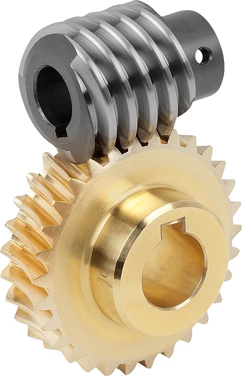
What is the lifespan of a typical worm gear?
The lifespan of a typical worm gear can vary depending on several factors, including the quality of materials, design, operating conditions, maintenance practices, and the specific application. Here’s a detailed explanation of the factors that influence the lifespan of a worm gear:
1. Quality of materials: The choice of materials used in the construction of the worm gear greatly impacts its lifespan. High-quality materials, such as hardened steel or bronze, offer better durability, wear resistance, and overall longevity compared to lower-quality materials. The selection of appropriate materials based on the application requirements is crucial for achieving a longer lifespan.
2. Design considerations: The design of the worm gear, including factors such as tooth profile, size, and load distribution, can influence its lifespan. Well-designed worm gears with optimized tooth geometry and proper load-carrying capacity tend to have longer lifespans. Additionally, features like lubrication systems and anti-backlash mechanisms can also contribute to improved durability and extended lifespan.
3. Operating conditions: The operating conditions under which the worm gear operates play a significant role in determining its lifespan. Factors such as load magnitude, speed, temperature, and environmental conditions can affect the wear and fatigue characteristics of the gear. Properly matching the worm gear to the application requirements and ensuring that it operates within specified limits can help prolong its lifespan.
4. Maintenance practices: Regular maintenance and proper lubrication are essential for maximizing the lifespan of a worm gear. Adequate lubrication helps reduce friction, wear, and heat generation, thereby extending the gear’s life. Regular inspections, lubricant replenishment, and timely replacement of worn or damaged components are important maintenance practices that can positively impact the lifespan of the worm gear.
5. Application-specific factors: The specific application in which the worm gear is used can also influence its lifespan. Factors such as operating cycles, torque levels, shock loads, and duty cycles vary between applications and can impact the wear and fatigue experienced by the gear. Understanding the unique requirements and demands of the application and selecting a worm gear that is appropriately rated and designed for those conditions can contribute to a longer lifespan.
Given the variations in materials, designs, operating conditions, and maintenance practices, it is challenging to provide a specific lifespan for a typical worm gear. However, with proper selection, installation, and maintenance, worm gears can have a lifespan ranging from several years to decades, depending on the factors mentioned above.
It is worth noting that monitoring the performance of the worm gear through regular inspections and addressing any signs of wear, damage, or excessive backlash can help identify potential issues early and extend the gear’s lifespan. Additionally, following the manufacturer’s guidelines and recommendations regarding maintenance intervals, lubrication types, and operating limits can significantly contribute to maximizing the lifespan of a worm gear.
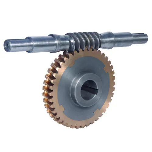
How do you retrofit an existing mechanical system with a worm gear?
When retrofitting an existing mechanical system with a worm gear, several considerations need to be taken into account. Here’s a detailed explanation of the retrofitting process:
- Evaluate the existing system: Before proceeding with the retrofit, thoroughly assess the existing mechanical system. Understand its design, function, and limitations. Identify the specific reasons for considering a worm gear retrofit, such as the need for increased torque, improved efficiency, or enhanced precision.
- Analyze compatibility: Evaluate the compatibility of a worm gear with the existing system. Consider factors such as available space, structural integrity, alignment requirements, and the load-bearing capacity of the system. Ensure that the addition of a worm gear will not compromise the overall performance or safety of the system.
- Select the appropriate worm gear: Based on the requirements and constraints of the retrofit, choose a suitable worm gear. Consider factors such as gear ratio, torque capacity, efficiency, backlash, and mounting options. Select a worm gear that matches the specific needs of the retrofit and is compatible with the existing system.
- Modify or adapt the system: Depending on the compatibility analysis, it may be necessary to modify or adapt certain components of the existing system to accommodate the worm gear. This can involve making adjustments to shafts, bearings, housings, or other mechanical elements. Ensure that any modifications or adaptations are carried out with precision and adhere to industry standards.
- Install the worm gear: Install the selected worm gear into the modified or adapted system. Follow the manufacturer’s instructions and guidelines for proper installation. Pay attention to torque specifications, lubrication requirements, and any specific assembly procedures. Ensure that the worm gear is securely mounted and aligned to minimize misalignment and maximize performance.
- Test and optimize: After the installation, thoroughly test the retrofitted system to ensure its functionality and performance. Conduct tests to verify torque transmission, efficiency, backlash, noise levels, and any other relevant parameters. Monitor the system during operation and make any necessary adjustments or optimizations to fine-tune its performance.
- Document and maintain: Document the retrofitting process, including any modifications, adjustments, or optimizations made to the existing system. Keep records of installation procedures, test results, and maintenance activities. Regularly inspect and maintain the retrofitted system to ensure its continued performance and reliability.
It’s important to note that retrofitting an existing mechanical system with a worm gear requires expertise in mechanical engineering and an understanding of the specific system requirements. If you lack the necessary knowledge or experience, it is advisable to consult with professionals or engineers specializing in power transmission systems to ensure a successful retrofit.
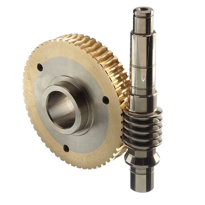
How do you calculate the gear ratio of a worm gear?
Calculating the gear ratio of a worm gear involves determining the number of teeth on the worm wheel and the pitch diameter of both the worm and worm wheel. Here’s the step-by-step process:
- Determine the number of teeth on the worm wheel (Zworm wheel). This information can usually be obtained from the gear specifications or by physically counting the teeth.
- Measure or determine the pitch diameter of the worm (Dworm) and the worm wheel (Dworm wheel). The pitch diameter is the diameter of the reference circle that corresponds to the pitch of the gear. It can be measured directly or calculated using the formula: Dpitch = (Z / P), where Z is the number of teeth and P is the circular pitch (the distance between corresponding points on adjacent teeth).
- Calculate the gear ratio (GR) using the following formula: GR = (Zworm wheel / Zworm) * (Dworm wheel / Dworm).
The gear ratio represents the speed reduction and torque multiplication provided by the worm gear system. A higher gear ratio indicates a greater reduction in speed and higher torque output, while a lower gear ratio results in less speed reduction and lower torque output.
It’s worth noting that in worm gear systems, the gear ratio is also influenced by the helix angle and lead angle of the worm. These angles determine the rate of rotation and axial movement per revolution of the worm. Therefore, when selecting a worm gear, it’s important to consider not only the gear ratio but also the specific design parameters and performance characteristics of the worm and worm wheel.


editor by CX 2023-10-03